Portable L. Drault Induction Coil f/ X rays
This coil was obtained from
The coil was apparently in
This was a comment supplied by
the originator of the coil:
“Well, the coil was a part
of a small laboratory in
The
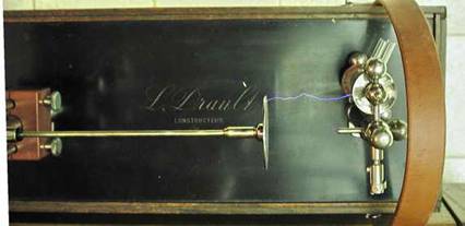
coil was used for X rays and was made by L. Drault. Numerous pieces are marked
by the manufacture, the coil top, meters, mercury interrupter armature and top
and the phenolic back and bottom block of the meter post.


The
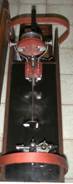
coil is unique in that it was designed with a mercury interrupter as standard.
The interrupter was driven by the electromagnetic filed generated by the
primary coil of the coil.
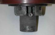
The
rectangular piece of metal seen behind the pot is the core of the coil. The
rotor of the interrupter is in alignment with this metal.
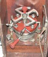
The
interrupter has an internal rotor that has two simple spiral tubes inside it.
When rotating, this pumps the mercury up and out the 2 jets. The 2 streams of
mercury make contact with 4 arced pieces of metal mounted underneath the top of
the interrupter. This effectively shorts across the 2 arms on the top of the
interrupter. The mercury allows high currents and quick breaks for a very rapid
coil charging.
The
interrupter gives 4 breaks per revolution corresponding to each arm position of
the external armature.
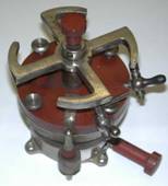
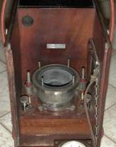
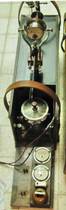
The
long knob locks the pot in a certain position. The pot was rotated to vary the
speed of the interrupter. It did this by changing the timing of the voltage
applied to the coil in relation to the rotor position. The external swastika
shaped armature is timed to the internal rotor by a set screw in the armature
and a hole in the rotor shaft.
Lubrication
of the rotor shaft is accomplished by a small oil hole thru the hub of the
external rotor which directs the oil to the shaft bearing mounted in the
insulated top.
Situated
inside the wooden mounting base of the interrupter is a condenser connected
across the interrupter.
2
binding posts are also mounted to the interrupter contacts which serve to
connect an external interrupter if desired.
The
2 pet cocks on the interrupter were used to purge the internals of the pot with
coal gas. This was to reduce oxidation of the mercury and components. It was
very important to make sure all air was displaced with gas before operating the
turbine or it could explode! Although the gas was flammable, if there was no
oxygen to sustain combustion, the gas was inert.
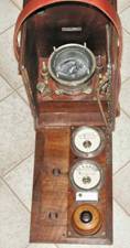
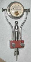
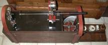
Most
portable coils were very simple in that they had a pair of binding posts to
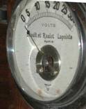
connect the battery. This coil has a complete control panel comprised of an
ammeter, 0-15 ADC, and a voltmeter, 0-30 VDC, a simple lead wire fuse block and
an ON/OFF switch.
The
ammeter is always connected to the coil and the voltmeter has a push button to
temporarily monitor the battery voltage. The voltmeter has a very low
resistance and would drain the battery if left connected, hence the push button
to momentarily place the meter in the circuit.
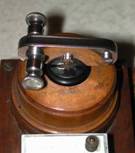
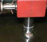
The
ON/Off switch is interesting in that it is also where the power is applied to
the system. The rectangular slot on top of the switch has a pair of contacts
situated across from each other where the batter power would come in.
The
switch has a red line on one side of the slot to indicate the polarity side of
the battery. If the battery is connected with the + corresponding the red line,
the polarity is correct for the coil and meters. This would make the HV
connections of the coil always be the same polarity as well and simplifies
connecting the X-ray tube.
The
power plug was also the key to turn the coil on. The original plug was missing
so a new plug/ key was fabricated trying to keep the look with the period of
the coil.
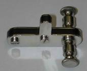
The
HV posts for the coil are very interesting in themselves. The bases of both
posts are slotted to lock them in a fixed orientation on the coil top.
The
meter post has a milli-ammeter incorporated in it. The meter was used to
monitor tube current and it is in series with the coil. The meter range is 0-3 ma.
There
is a large hole in the meter post and it is directly in line with a point on
the other post. It is assumed there would have been a spark gap on the coil as
this was a common on X ray coils.
The
gap was set a certain distance to determine the “hardness” of the X ray tube.
When the tube was operating, the gap was set to a certain distance for the
particular X ray work to be done and to determine the hardness or vacuum level
of the tube. For example, most work was typically 3” of spark.
When
the coil was running, the spark gap was adjusted until a spark would pass
across the gap. This distance was what the tube would “back up”. By knowing
this distance, the proper tube could be selected for the desired operation.
A
spark rod was made for this post.
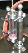
The
second post is very interesting. There is a series spark gap mounted on this
post. All connections seem to have been made after this gap.
Series
gaps were used on induction coils to block inverse currents when the
interrupter was first energized. This inverse was of opposite polarity and much
lower voltage for the X ray tube and can shorten the life of the tube or even
damage it if the inverse was high enough. The gap was set to prevent the lower
voltage from jumping the gap and being applied to the tube and would fire when
the correct and higher voltage was produced from the coil.
This
apparent series gap is adjustable and is enclosed in a glass cylinder with 2
connections. The exact purpose of the connections is not known yet and it is
assumed an inert gas was circulated thru the tube to reduce oxidation of the
metal when the gap was operational. So far, I cannot locate any references to
this particular arrangement.
Of
interest, the posts could not be stored in the coil and it is amazing they
remained with the coil all these years.
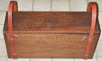
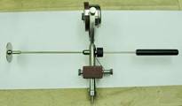
One
would be hard pressed to truly call this a “portable” coil. It measures 6 ½”
wide by 22 ¼” long and 10 ¼” tall and weighs 57 pounds without the HV posts and
60 pounds with the posts!
A
suitable battery would have weighed at least 30 pounds. The total outfit with a
tube and stand was probably approaching 100 pounds!
Operation
of the coil would have been something like this:
The
coil was opened and set up with the battery wires connected to the plug and the
X ray tube connected to the appropriate posts of the coil.
The
plug was inserted in the switch and the pushbutton checked to verify the
battery had a good charge.
The
switch was turned on, at this point, the coil is ready to run but there is no
current flowing thru the coil yet.
The
red knob on top of the interrupter is given a quick twist clockwise to pump
some mercury and start the coil. If the twist is fast enough, the coil will
start and the interrupter will run and come up to speed of approximately 700-800
RPM with a quite bump, bump, bump.. noise. This is equivalent to 2800-3200
breaks per minute for the coil.
The
spark gap can be set to verify the resistance of the tube or tubes so the
proper tube can be selected for the desired X ray. At the same time, the tube
can be viewed with a hand held fluoroscopic screen to verify it is operating
properly.
The
switch was turned off to stop the operation.
Once
the system was verified, the patient was placed under the X ray tube and the
desired exposure was made.
Exposure
times could take up to an hour back then and a stop watch was a necessary
accessory to the Dr.’s X ray routine.
This
is a rare find and a thrill to see it operational once again.
Frank
Jones