Tesla Coil Installation for Public Viewing: |
|||||||||||
EMI, Gaseous Emission, Acoustic Noise |
|||||||||||
And Discharge Control |
|||||||||||
|
|||||||||||
Abstract
The public display of Tesla Coils can result in concerns on potential safety issues, including electromagnetic interference (EMI), gaseous emissions, and acoustic noise. The potential concern becomes significant for large size apparatus. The corona discharge output of these coils must be controlled to deliver deliberate arc paths, and ambient lighting should be selected to provide visual contrast. These potential safety and aesthetics issues can be addressed in an effective display. An installation example is described.
Introduction
Public displays of Tesla Coils have been popular for many years and are commonly seen at fairs, museums, schools, and special events. The popularity of Tesla Coil displays can be anticipated to continue, and new displays will be developed. Concurrently, the public has become increasingly concerned about safety issues in recent years, and has a more general awareness of radiation hazards, electromagnetic interference, and air and chemical pollution. Moreover, restrictions from governmental agencies such as OSHA and the FCC and guidelines from technical groups such as ANSI and the IEEE have been, and will continue to be, issued to protect the public from a wide variety of potential hazards.
An effective Tesla Coil display can alleviate potential safety concerns. Such displays can be designed to control EMI, gaseous emissions, and acoustic noise levels, and at the same time, can be constructed to limit ambient lighting and provide a controlled corona discharge. An installation example will be used to describe such a Tesla Coil display.
Installation Example
The installation of a large Tesla Coil at the Museum of Science and Industry in Tampa, Florida, will be described. The director of the museum selected a custom-built Tesla Coil for this display. This installation was made at the main building of the museum, which is not wholly enclosed from the outside. A decision was reached in the initial planning to develop an artificial environment to provide uninterrupted operation of the coil with the climatic variations in that locale. This particular display required daily operation on an automatic basis. The overall display was required to blend with the "turn of the century" motif used in the museum throughout their Electric Plaza section. The installation also had to provide a very close-up view of the Tesla Coil operation from a semicircular walkway.
 The first step in developing this display was to devise a suitable floor
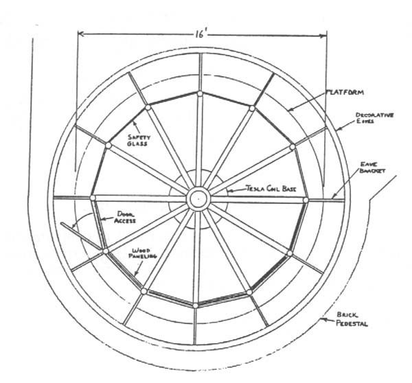
plan. Sufficient floor areas are required to accommodate the enclosure for the Tesla Coil
and its corona discharge path(s) as well as a viewing area for the public. In this case,
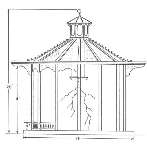
the overall enclosure size for the Tesla Coil is 20 feet high and 16 feet in diameter. The
overall plan and elevation views of this installation are shown in Figures 1 and 2,
respectively. This particular installation is stand-alone rather than built-in, however,
in both cases, the display enclosure itself can be treated as an integral component.
The first step in developing this display was to devise a suitable floor
plan. Sufficient floor areas are required to accommodate the enclosure for the Tesla Coil
and its corona discharge path(s) as well as a viewing area for the public. In this case,
the overall enclosure size for the Tesla Coil is 20 feet high and 16 feet in diameter. The
overall plan and elevation views of this installation are shown in Figures 1 and 2,
respectively. This particular installation is stand-alone rather than built-in, however,
in both cases, the display enclosure itself can be treated as an integral component.
 The actual geometry used in the enclosure is a dodecagonal cylinder. Six
of the sides are wood paneled, and the remaining six sides are glass. The wood paneling
reduces the ambient lighting as required for daytime viewing. An access door is located in
one of these panels, and primary and secondary interlock switches are provided to prevent
inadvertent operation during servicing periods. Details of the enclosure construction are
shown in Figures 3 and 4. Installation features include provision for EMI, gaseous
emission, and acoustic noise controls, which will be described in turn.
The actual geometry used in the enclosure is a dodecagonal cylinder. Six
of the sides are wood paneled, and the remaining six sides are glass. The wood paneling
reduces the ambient lighting as required for daytime viewing. An access door is located in
one of these panels, and primary and secondary interlock switches are provided to prevent
inadvertent operation during servicing periods. Details of the enclosure construction are
shown in Figures 3 and 4. Installation features include provision for EMI, gaseous
emission, and acoustic noise controls, which will be described in turn.
Tesla Coil Description
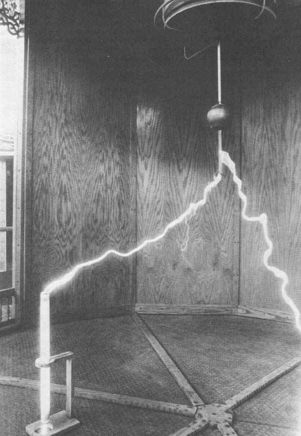
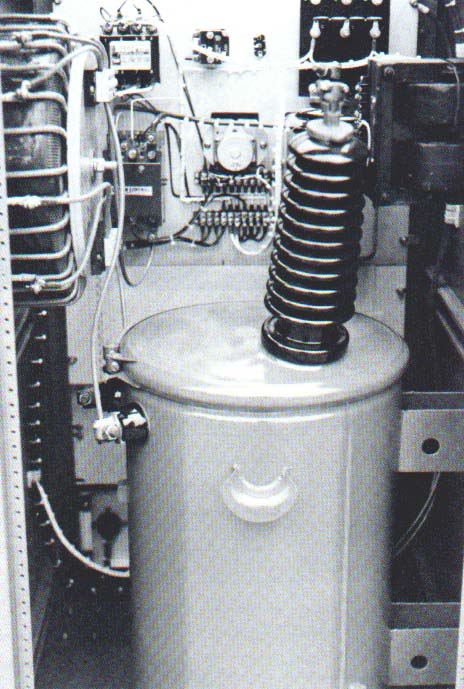
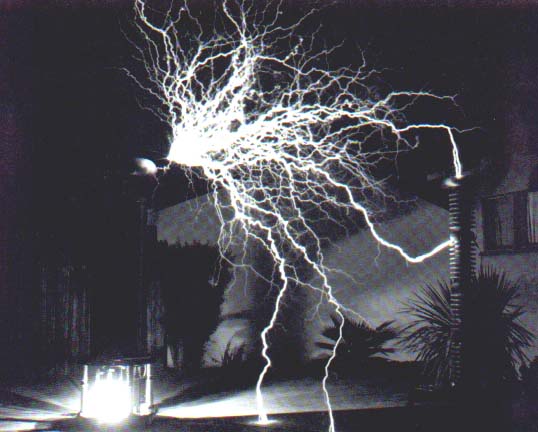
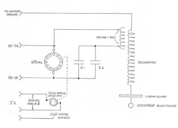
The Tesla Coil used in this display is a custom-built Model 9 unit, fabricated by Professional Sound Systems - Ultra High Voltage Division [1]. This coil is shown in Figure 5. This coil requires a main AC input of 12.5 kVA, 208 VAC, and single phase. The power supply, with external controls, is located in a separate room. An internal component view of the power supply is shown in Figure 6. This Tesla Coil is capable of corona discharges up to 15 feet in length. The full discharge capability is shown in Figure 7. This coil has a resonant frequency of approximately 85 kHz. Figures 8 and 9 are schematics of the Tesla Coil and power supply, respectively.
The secondary coil is 21 inches in diameter and uses PVC insulated #22 AWG stranded
copper wire closely wound on a phenolic tube 65 inches long. This coil has a corona guard
ring at the top of the winding to prevent damage to the secondary coil. The 4-inch
diameter hollow copper discharge electrode was selected by the customer in preference to
the standard 30-inch diameter aluminum toroid normally supplied with this coil.
The base unit shown in Figure 10 consists of the Tesla primary coil, rotary spark gap, and oscillation capacitors. The spark gap has two stationary sets of electrodes and a phenolic disk containing 12 equally spaced rotating electrodes. The rotary electrodes are arbor driven by a 1/2-hp 3,450-rpm drive motor.
The primary coil, shown in Figure 11, consists of 4 1/2 turns of 1/2-inch diameter copper tubing with a 30-inch outside diameter and 1-inch turn-to-turn spacing. Adjustable brass clamps connect the coil with the #1 AWG wiring used in the primary circuit. The placement of the base unit components was selected for this custom installation. The secondary coil is attached to the base unit with three machine screws for ease in assembly and disassembly. This Tesla Coil is designed to be suspended upside down from a ceiling mount.
EMI Control
This installation uses a full Faraday shield to reduce EMI. The shield was fabricated from 1-inch square stainless steel wire mesh carefully connected to provide an effective shield. The mesh is spaced 1 inch from the inside of the quarter-inch safety glass panels of the enclosure. This mesh is visible in Figures 3 and 4. The mesh is laminated into the wood paneling forming the rest of the structure. The jam of the access door is lined with copper sheeting which bonds the mesh in the wood paneling to the mesh laminated in the access door. The mesh is bonded at all framework joints including the aluminum tee channels used to join the glass panels, and copper strips overlap both the floor and ceiling sections of the enclosure. The ceiling panel sections are fabricated from copper sheeting lining the wood paneling. The entire display enclosure is bonded to earth ground and to the steel building frame with #1 AWO stranded copper wire. All electrical circuits interconnected between the power supply rack and the Tesla Coil base unit are run in solid metal conduits, which are grounded. This installation provides effective EMI control.
Gaseous Emission Control
Tesla Coils of this size generate large quantities of ozone and oxides of nitrogen from the high voltage discharge chemical reaction with the atmosphere. If left to accumulate, these gases would be corrosive to the coil components and would aggravate the secondary coil insulation breakdown. Moreover, human exposure to high concentrations of these gases can result in headaches, nausea, and dizziness. An air filtration system has been effectively used to vent these gases to the outside. The air filtration system contains a dehumidifier, and has sufficient pump power to maintain a small positive pressure within the enclosure.
Acoustic Noise Control
Tesla Coils of this size also generate a significant amount of acoustic noise from the
rotary spark gap and high voltage discharge. The acoustic noise level for the Model 9 coil
is 100 dBa SPL on an a-weight scale at a 12-foot range. This measurement was performed
with a 1/3-octave spectrum analyzer and the Model 9 coil operating in an open-air
environment, at full power. The design of this enclosure effectively attenuates the noise
generated by the coil by more than 20 dB, and permits close public viewing without
objectionable sound levels. Clear silicon sealant was carefully applied to all joints of
the enclosure during assembly. This sealing is mutually effective for both the air
filtration system and the control of acoustic noise.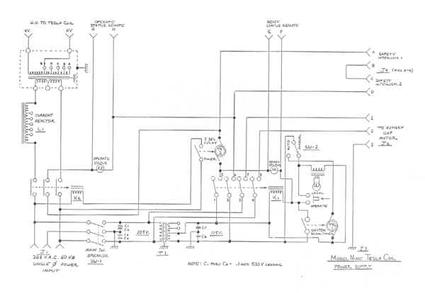
Conclusions
Potential concerns of EMI, air, and noise pollution are present in the public display
of Tesla Coils. New federal restrictions and industry guidelines mandate strict emissions
standards. The use of a full Faraday shield enclosure provides effective control of EMI
radiation for a Tesla Coil public display. Properly selected enclosure materials reduce
acoustic noise. An air filtration system in the enclosure controls and removes
concentrations of gaseous emissions generated by Tesla Coils.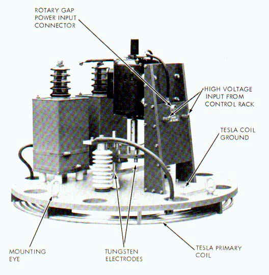
Acknowledgement
It is the author's privilege to thank Mr. William W. Ray, Director, at the time of installation, of the Museum of Science and Industry in Tampa, Florida, for valuable guidance in establishing the exhibit.
 About The Author
- Produced by W.C. Wysock. Professional Sound Systems -- Ultra High Voltage Division (brochure). 2527 Treelane Ave. Monrovia, CA.
- Federal Communications Commission. Rules and Regulations, Vol. II. parts 2, 5, 15, 18. October 1982.
- "American National Standard Safety Levels with Respect to Human Exposure to Radio Frequency Electromagnetic Fields, 300 KHz to 100 GHz," (ANSI C95.1-1982) IEEE, 1982.
- Nahman, Kanda, Larsen, and Crawford. IEEE Transactions on Instrumentation and Measurement, Vol. IM-34, No. 4. December 1985.
- Lerner, Eric J., Editor. "The Drive to Regulate Electromagnetic Fields," IEEE Spectrum. March 1984. p. 63-70.
- "Radio Frequency (RF) Sealers and Heaters: Potential Health Hazards and Their Prevention." Joint N.I.O.S.H./O.S.H.A., Current Intelligence Bulletin 33. December 4, 1979.
- "Threshold Limit Values and Biological Indices for 1985-1986," American Conference of Governmental Industrial Hygienists, ISBN: 0-936712-61-9, p. 86-91.
- Osepchuk, John M. Biological Effects of Electromagnetic Radiation. IEEE Press, 1983.
- Skomal, Edward N. Man-Made Radio Noise. Van Nostrand Reinhold Company, 1978.
c 1986, Int'l Tesla Society, Inc. 2-102